by Jean Fourcade
Jean Fourcade works for the French Space Agency where he is involved in the computation of satellite trajectories. He has been flying gyros in the south-west of France for five years and one of his hobbies is studying flight mechanics and aerodynamics of the autogyro.
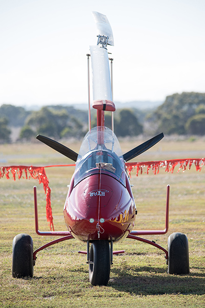
Longitudinal stability of gyroplanes
The longitudinal stability of the gyroplane has always been a subject of passionate debate between pilots. The phenomena involved, which are pilot induced oscillation (PIO) and power push over (PPO), were discussed in some articles in ROTORCRAFT magazine and in some classical gyro books. However, the University of Glasgow has made a complete mathematical study of this problem only recently. This work was funded under the UK Civil Aviation Authority and consisted of a parametric study of gyroplane longitudinal stability.
This study concluded, ‘the longitudinal stability of the gyroplane is largely insensitive to a wide range in design characteristics. However, an exception was found to be the vertical location of the propeller thrust line in relation to the centre-of-mass. Stable or unstable configurations could be found depending on the height of the propeller thrust line’.
A complete study of longitudinal stability of the gyroplane is beyond the scope of this article. However, some simple considerations can be shown, so that everyone can understand the principles of stability and how it affects gyro design.
There are two ways of studying stability in aircraft science, static stability and the dynamic stability.
Static stability, as the name implies, is not concerned with mass or inertia characteristics of the aircraft. It is only a geometric criterion.
Dynamic stability is the most complete study of stability, but is also, by far, the most complex. It requires writing equations of motion of the trimmed aircraft, and seeing how the aircraft responds to an arbitrary perturbation (disturbance).
The dynamic stability of gyroplanes is not very different from the dynamic stability of other aircraft. As for aeroplanes and helicopters, there are two oscillating modes; the short period mode and the long period mode (also called phugoid mode). The short period mode is an oscillation of the pitch of the aircraft at mainly constant speed while the phugoid mode is an oscillation of the pitch at a mainly constant angle of attack.
The point which differs from other aircraft (even from helicopters) is that there is one more degree of freedom which is the rotor speed and it can be shown that there is some coupling between rotor speed and phugoid mode which indicates a potential handling problem as the phugoid mode can be unstable.
The purpose of this article is to deal only with static stability which can be understood without the need of an extensive mathematical background but is of great importance in understanding the correct placement of the Centre of Gravity (CG) relative to forces involved in the longitudinal motion,
Let us examine the definition of the static stability.
It is common usage in engineering science that when you want to study stability relative to a given parameter, you plot a curve where the x coordinate represents the parameter involved and the y coordinate the acceleration (or something proportional) of this parameter. The longitudinal motion of a gyroplane is described by five parameters: the air speed, the angle of attack of the fuselage, the pitch attitude, the pitch angular velocity and the rotor speed. Therefore, static stability can be studied for each of these parameters. We will consider in this study only the angle of attack, which is one of the most important.
The longitudinal pitch motion of the gyro is due only to the pitch moment of forces acting in the longitudinal plane. Therefore, to study the static stability relative to the angle of attack, we have to plot pitching moments versus the angle of attack and see how these moments vary.
The sign convention is generally positive angle of attack when nose up (and then positive pitching moments are nose-up moments).
It is obvious that to fly in trimmed condition, the pitch must be constant and for that, the total moment computed with all forces involved must be equal to zero. Therefore, trimmed points belong to the x-axis.
The definition of the static stability can be defined as follows. We will say that the gyro is stable with an angle of attack when a variation of the trimmed angle of attack will induce a moment which tends to return the gyro to its previous trimmed condition.
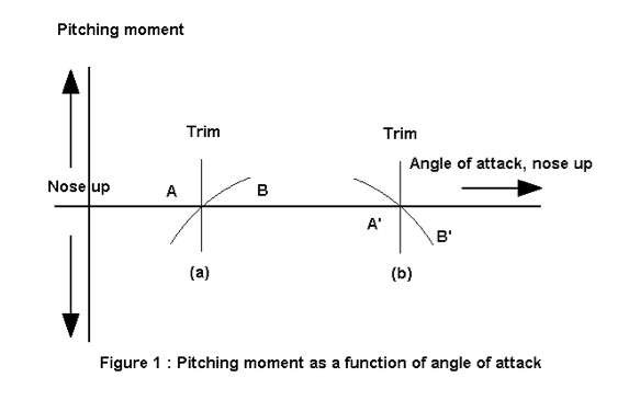
Let us examine case (a) of Figure 1 where the trim is point A. Let us consider a disturbance which increases the angle of attack up to point B (a vertical gust for example). As the angle of attack has changed, the pitching moment is no longer equal to zero and we can see in Figure1 that point B is not trimmed because it is not on the x-axis. As the slope of the curve in this example is positive, it appears as a nose up pitching moment that will increase the pitch of the gyro and then the angle of attack. Therefore, case (a) is unstable because when a disturbance increases the angle of attack, the gyro reaction is to magnify this phenomenon.
On the other hand, case (b) is stable because when a disturbance increases the angle of attack up to point B’, the pitching moment which appears is negative and acts in a way to reduce the angle of attack until the gyro returns to its previous trimmed condition (point A’).
Therefore, the static stability depends on the slope of the curve on points of the x-axis or in other words, in the derivative of the pitching moment relative to the angle of attack. The condition of static stability is that the derivative must be negative.
Let us apply this rule to the forces acting on the gyro.
There are four main longitudinal forces acting on a gyro:
1. propeller thrust
2. horizontal stabiliser thrust (lift and drag)
3. body drag
4. rotor thrust (lift and drag).
To compute the stability given by each of these forces, we have to evaluate the derivative of their pitching moment and see what is the best placement of the CG so that these derivatives are negative.
a) Propeller thrust
For a given engine RPM, the propeller thrust depends on the speed of the gyro but is not very sensitive to the angle of attack. We can consider, at first order, that the moment of the propeller thrust is independent of the angle of attack and then, find the derivative of this moment is equal to zero. Therefore, the propeller thrust by itself has no impact on longitudinal stability (we say, in this case, that the trim is indifferent). The CG may be up or down the thrust line or before or behind the propeller. We will go back on that assertion later on.
b) Horizontal stabiliser
It is well known that the horizontal stabiliser must be placed at the tail of an aircraft. As a matter of fact, it can be demonstrated that the derivative of the pitching moment is negative when the centre of pressure of the thrust (the point where the drag and the lift are applied) is behind the CG.
Therefore, a horizontal stabiliser adds stability.
The efficiency of the stabiliser is greater when the moment arm is longer and when the aerodynamic lift is greater.
To increase the moment arm, we have to place the stabiliser far behind the CG and to increase the lift we have to increase the surface area of the stabiliser.
It is important to note that the lift is proportional to the square of the air speed, whereas it is only proportional to the angle of attack. It is therefore preferable to place the stabiliser in the slipstream of the propeller to use the benefit of more air speed. It is especially important in a gyro, as these machines are not flying quickly.
c) Body drag
The body drag is an aerodynamic force. As with a horizontal stabiliser, the centre of pressure must be behind the CG to have a negative derivative moment.
However, the computation of the derivative of pitching moment is not simple in practice because the centre of pressure strongly varies with angle of attack. Experience shows (and it is particularly true on full enclosure machines) that the derivative of the moment with respect to angle of attack tends to be positive. The contribution of body drag is therefore destabilising.
d) Rotor thrust
The main difference between different designs of gyros comes from the horizontal placement of the CG relative to the rotor thrust line.
The phenomenon that is involved is called ‘instability of the rotor relative to the angle of attack’, and is well-known in the helicopter world.
To explain in detail this phenomenon, we have to study the case where the CG is in front of the rotor thrust line and the case where the CG is behind the thrust line. We will see that the first configuration is stable, whereas the second is unstable.
Let’s consider Figure 2, where the CG of the gyro is behind the rotor thrust line. When trimmed, the thrust of the rotor is the vector noted (a) on the figure.
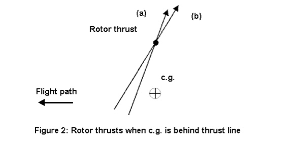
Suppose that there is a gust which increases the angle of attack.
An increase of the rotor angle of attack will increase the thrust of the rotor. It will also increase the difference of thrust between the advancing blade and the retreating blade that will then increase the cyclic flapping angle. As the rotor thrust is, at first order, perpendicular to the tip path plane, an increase of the cyclic flapping angle will tilt the thrust rearward. The rotor thrust after the gust is represented by the vector (b) on Figure 2.
Now what is the consequence of the rotor pitching moment?
As the CG is behind the thrust line of the rotor, the pitching moment induced by the rotor is positive (nose up). An increase of the thrust will increase the moment. The fact that the thrust tilts rearward will increase the length of the moment arm and then the moment. Both phenomena act in the same way: an increase of angle of attack will increase the moment.
Therefore, the derivative of the moment relative to the angle of attack is positive. This configuration is unstable.
To summarise, when CG is behind the rotor thrust line:
Increase Angle of Attack (AOA) => increase thrust and flapping => both increase moment => increase AOA: unstable
Now imagine that the CG is in front of the thrust line of the rotor as shown in Figure 3. This time the rotor induces a negative pitching moment (nose down).
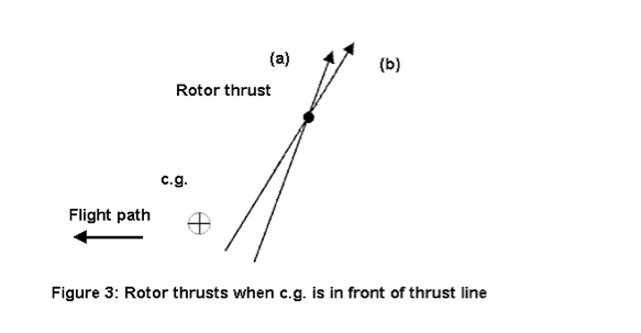
When a gust increases the angle of attack, the rotor reacts the same way as before. We have an increase of the thrust and the cyclic flapping angle.
But now what is the effect of the pitching moment?
An increase of thrust will increase the absolute value of the moment (more nose down moment). As the moment is negative, this will lower the moment.
The cyclic flapping angle will reduce the moment arm length (as shown in Figure 3) and then decrease the absolute value of the moment. This time, the two phenomena don’t act in the same way but it can be demonstrated that it is the variation of thrust that is most important. So this time, an increase of angle of attack will decrease the moment. The derivative is therefore negative and this configuration is stable.
To summarise when CG is in front of the rotor thrust line: Increase AOA ~> increase thrust and flapping ~> decrease moment => decrease AOA: stable.
Hence, the stable condition for a rotor is that its pitching moment must be strictly negative. Furthermore, the stability increases when the moment decreases.
The rotor thrust is the main force acting on the gyro and the value of its derivative is also the biggest one. Therefore, one can understand that the horizontal placement of the CG relative to the rotor thrust line is of great importance.
The question now is how can we design a gyro so that the moment coming from its rotor is negative?
We will see that the implementation of this condition mandates a condition on the vertical placement of the CG relative to the propeller thrust line and the reason for that comes from trim.
Let’s suppose, for simplicity, that the gyro has no horizontal stabiliser and that the pitching moment coming from the body drag is negligible (we will come back to this assertion). Hence, there are only two forces acting on the gyro: the propeller thrust and the rotor thrust.
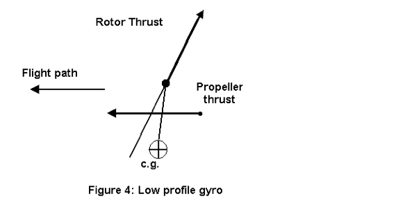
Let us consider Figure 4, where the CG is below the propeller thrust line as are most Bensen-derived gyros (low profile gyro).
We can see in that figure that the engine induces a nose-down pitching moment.
To be in trim, the rotor must induce a nose up (positive) pitching moment and for that, the CG must be behind the rotor thrust line. Such a gyro is therefore unstable in angle of attack.
On the other hand, if you have a CG which is above the engine thrust as shown in Figure 5, then the moment coming from the engine is a nose-up moment and to trim the gyro, the rotor must induce a nose-down moment. For that, the CG must be in front of the rotor thrust line. Such a gyro is stable in angle of attack.
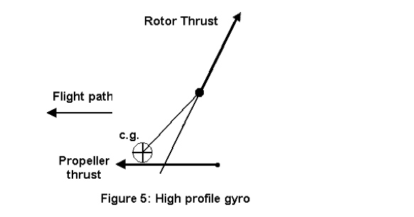
Such a design is called centreline thrust or high profile gym. The propeller thrust line is close, but below the CG.
The flight characteristics of such gyros differ from traditional low-profile machines.
Contrary to a low-profile gyro, this kind of machine has a good response to change of throttle. When you add more throttle, there is a more nose-up moment and then the pitch increases, which is the response you desire when you want to gain altitude. Similar reasoning applies when you reduce throttle.
One cannot help but wonder whether such a gyro is dangerous in a power failure?
Flight tests have shown that it isn’t. When you have a power failure in a low-profile gyro, you must rapidly push the stick forward to avoid a decrease of the air speed and to nose down the machine. In a high-profile gyro, the vanishing of the nose-up moment coming from the engine will naturally nose down the machine. You only have to hold the stick firmly.
In our previous reasoning to compute the trim, we have neglected the moment coming from the body drag of the machine. The value of this moment depends on the vertical position of the drag centre relative to CG. Generally, the tendency of such moment is to be nose down and destabilising, as we said before. The fact that it is a nose-down moment decreases stability because, to trim, it forces the rotor moment to increase. This phenomenon is worse at high airspeed. To counteract that, we have to add a horizontal stabiliser with an initial negative angle of attack so that the nose- up pitching moment coming from the stabiliser increases when speed increases. The stabiliser will compensate the nose-down moment coming from the body drag and its lack of stability.
Now, what is the relation between what was said and Pilot Induced Oscillation (PIO) and Power Push Over (PPO)?
What I don’t really like in the term PIO is that it suggests that the pilot is totally the cause of oscillations and that this phenomenon has nothing to do with the machine. This suggestion is wrong. The pilot has a part of the responsibility because he emphasises the oscillations. But the stability characteristics of the gyro are largely responsible. It is preferable, from my point of view, to speak about stability or instability. As PIO can be considered as a lack of stability, what was said should convince pilots that a high-profile gyro with a horizontal stabiliser is less prone to PIO than any other gyro design.
Now I would like to add a few words about PPO.
PPO is different than PIO. A machine which is more prone to PIO can be handled quite well with sufficient training, whereas PPO can occur suddenly when you are flying in windy conditions. The most dangerous thing is that this phenomenon occurs without warning.
When you are flying a low-profile machine without horizontal stabiliser and enter a downward gust, the rotor blades are suddenly unloaded. You have no more rotor thrust and the great nose-down moment coming from the engine suddenly bunts over the gyro.
It is possible to compute the time for such gyro to do a 180-degree rollover. Let us take for example a single place gyro which weighs about 330 pounds (150 Kgs). Let us suppose that the CG is I0 inches below the propeller thrust line and that the propeller thrust is about 200 pounds. To totally unload the rotor blade you need to hit a downward gust of about 40 feet per second. This is a strong gust but it can occur.
If the pilot does not react immediately by reducing throttle, it takes less than one second to do a 180-degree bunt over. One can understand the danger of this situation.
What can we do to avoid a 180-degree bunt over?
First, we must add a horizontal stabiliser. Due to the downdraft, the stabiliser will induce an opposite moment to prevent the bunt over.
Second, we must avoid having the engine create a nose-down moment when the rotor blades are unloaded. For that we have to put the engine thrust line close to the CG and a little bit below, so that it creates a nose-up moment. The nose-up moment will increase the angle of attack and again load the rotor blades.
Fortunately, solutions to avoid PPO are the same as those to reduce PIO.
In conclusion, here are my thoughts about designs of pusher gyros.
Low-profile gyros (which are the most common gyros) without a horizontal stabiliser are more prone to PIO due to the lack of stability and are DANGEROUS in terms of PPO. This kind of gyro must not be flown in windy conditions and not at high speed. (My personal point of view is that this kind of gyro should not be flown at all!).
Low-profile gyros with a true horizontal stabiliser are not the best, but are not the worst. By true stabiliser I mean a sufficient tail volume and a real aerodynamic profile. The horizontal stabiliser should be, if possible, in the slipstream of the propeller to be more effective.
High-profile gyros with true horizontal stabiliser are the best solution: they are less prone to PIO, and PPO is a non-issue. It is always possible to fly an unstable machine, but not for everyone. Even for a very good pilot an unstable machine is more dangerous than a stable machine.
by Don McCoy PhD. FGAA, A 894
Senior Lecturer in Physics, University of Adelaide
I have always had an interest in the physics of gyroplane control since I first flew one in 1963 (Pacific Ultralights May 1998 p. 25). More recently I became a certified trike pilot but have now finally returned to gyros.
Introduction
Over the years there has been an ongoing debate as to whether gyroplanes are aerodynamically, controlled or weight-shift controlled (Gyro News Winter 1991 p. 17 and p. 23) and there has been a number of articles describing the gyro as a weight-shift aircraft (Gyro News Winter 1989 p. 26, Summer 1990 p. 24).
The truth is that the control is entirely aerodynamic with gravity acting on the body of the gyro to provide the reference direction. The latter gives the illusion of weight shift which in fact it is not. The purpose of this article is to show how aerodynamics and physics explain this statement.
For the reader not familiar with the principles of gyroscopic precession of a rotating body, I suggest that the accompanying article titled ‘Gyroscopic precession: what is it when does it occur and how can I calculate it?’. Before continuing, let’s explain some definitions.
Definitions
A number of terms used in this discussion must be defined so that the explanations can be easily understood and use the terminology correct.
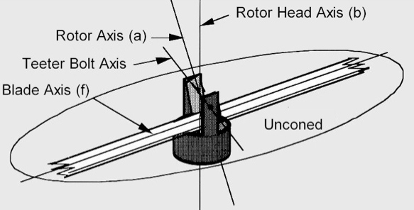
a. rotor axis: An axis through the centre of the teeter bolt and at right angles to the plane of rotation of the rotors defined b, the tips of the rotors during a complete rotation.
b. rotor head axis: An axis is through the centre of the teeter bolt and in line with the rotating shaft of the rotor head bearing.
c. flap angle: The angle between (a) and (b). It is also half the maximum angular oscillation between the blade axis and the rotor head axis. (Oscillation about the teeter bolt axis.)
d. mast axis: An axis through the centre of the teeter bolt and passing through the centre of mass of the gyroplane (loaded or unloaded).
e. fixed pitch: The angle of the chord of the rotor blades to the teeter bolt axis. (Note: not to the plane of rotation of the rotor blades)
f. blade axis: An axis parallel to the rotor blades running down the centre of the blades. (Ignoring coning which must be taken into account when considering rotor balance, loading and rotation rate, but is unimportant in the following discussion.)
g. teeter bolt axis: An axis along the length of the teeter bolt through its centre.
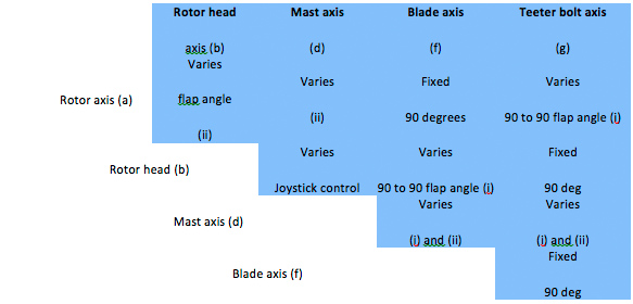
Some of the angles between these vectors are fixed and some vary. Those that vary during the rotation of the rotors are indicated (1) and those that vary during flight manoeuvres or wind gusts are indicated (ii). The table below summarises these relations.
Rotor control
For clarity, we will first consider a commonly held but totally incorrect explanation of how gyro rotors are controlled.
Say, we wish to make a right turn. the joystick is moved to the right and the weight of the gyro (because of weight shift) allows a torque to act on the rotor head through the control rods making the rotors tilt, thus banking and turning the gyro to the right.
Nothing could be further from the truth!
Reason… Firstly, the pivoting action of the teeter bolt prevents the control rod/rotor head assembly from exerting a torque directly on the rotor blades to change their plane of rotation. Secondly, if such a torque could be applied, the rotor would tilt forward and not to the right as the torque is in the forward direction (see accompanying article). Since this does not happen, it confirms that there is no direct torque applied to the rotor blades by the rotor head. If this were to happen, the gyro would be uncontrollable.
Explanation…
To understand why the teeter bolt prevents a direct torque acting on the rotor, consider the following:
a. When the rotor head axis is tilted towards the blade axis, there is free rotation about the teeter bolt axis so clearly no torque acts on the rotor (other than the negligible amount due to bearing friction).
b. When the rotor head axis is tilted perpendicular to the blade axis, it simply rotates the blades about the rotor blade axis. Again, no torque directly acts on the plane of rotation.
Since these two movements of the rotor head axis relative to the blade axis act in orthogonal (i.e. independent) directions, it follows that no significant direct torque can be exerted on the rotors due to rotation of the rotor head. Furthermore, since the rotor head cannot produce a direct torque to change the plane of rotation of the rotors, then by the action and reaction principle, the rotors cannot produce a direct torque on the rotor head to rotate the airframe of the gyro as required by a true weight-shift aircraft such as a hang glider or trike.
So what is the correct explanation of how the gyroplane is made to turn to the right?
The joystick is moved to the right causing the rotor head axis to tilt to the right and out of alignment with the rotor axis. The pivoting motion of the teeter bolt causes the pitch angle of the blades to van during the rotation, increasing the lift at the front and reducing it at the rear. The resulting large torque due to the aerodynamic effects of the change in pitch is directed to the right and causes the rotor axis (angular momentum of the rotors) to rotate to the right following the rotor head axis. As the rotor axis comes back in line with the tilted rotor head axis, the pitch angle ceases to vary and the lift from the front and rear rotor blade equalizes. Thus the torque vanishes and the rotors are tilted to the right to initiate the turn.
This short description needs further explanation.
It is well known that the action of the teeter bolt is to equalise the lift on the advancing and retarding rotors. The relation this has to gyroscopic precession will be discussed at the end of this article. What must also be understood is that the teeter bolt has a totally independent and equally important role of making the gyro controllable in flight. The teeter bolt causes the plane of rotation of the rotors to tilt in the correct direction for turn and bank, climb and descend, again by gyroscopic precession. It was explained earlier that, because of the teeter bolt, the rotor head cannot produce a direct torque on the plane of rotation of the rotors so the question then arises, what does? The answer is the aerodynamic effect of the air acting on the rotors. One can think of the rotors as ‘flying’ to align the rotor axis and the rotor head axis through gyroscopic precession.
References
Wheatley J.B. An aerodynamic analysis of the autogyro rotor with comparison between calculated and experimental results. NACA TR 4871.1934
Schad. J.L. Small Autogyro Performance, J American Helicopter Society, 10, 1965.
McKillip. R.M. and Chlh. M.H. Instrumented blade experiments using a light autogyro. Proceedings of the 16th European Rotorcraft Forum. Glasgow. Scotland. September 1990.