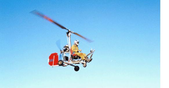
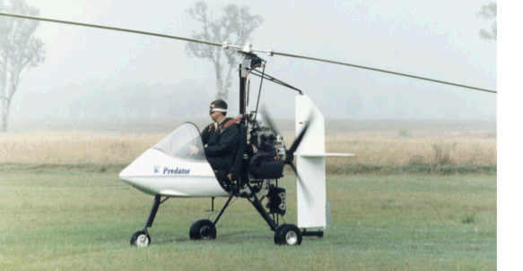
Gyroplanes derive lift from freely turning rotor blades tilted back to catch the air. The rushing air spins the rotor as the aircraft is thrust forward by an engine-driven propeller. Early gyroplanes were powered by engines in a tractor (pulling) configuration and were relatively heavy. Modern gyroplanes use a pusher propeller and are light and manoeuvrable. With the engine in the rear, the gyroplane has unobstructed visibility.
A gyroplane can fly more slowly than aeroplanes and will not stall. They can fly faster than helicopters but cannot hover. Since the rotor blades on the gyroplane are powered only by the air (autorotation), much like a windmill, there is no need for a tail rotor for anti-torque. The gyroplane is a stable flying platform. This is not so with helicopters, which pull the air down through engine-powered rotor blades making it possible to hover, but also making the aircraft very complicated and expensive to fly. Due to their inherent simplicity, gyroplanes are easier to operate and less expensive to maintain than helicopters.
Gyroplanes in flight are always in autorotation. If power fails in a gyroplane, the autorotation continues and the aircraft settles softly to the ground from any altitude. The procedure to land after a power failure is the same procedure as a normal landing, which requires no landing roll. Thus the gyroplane is a safer aircraft for low and slow flight, as compared with both helicopters and aeroplanes. The ability of gyroplanes to fly faster than helicopters and slower than aeroplanes makes it something of a hybrid, having the good qualities of the other two types of aircraft with little of the bad.
The single attraction of helicopters over gyroplanes is their ability to hover, which is necessary in some situations such as rescue or in sling load work. In air surveillance and point-to-point flying, not being able to hover is not a disadvantage because some gyroplanes take off and land vertically without having to hover. Helicopters at low altitude out of ground effect avoid hovering whenever possible. To fix surveillance on one spot, proper procedure for all rotorcraft is to circle in a slow orbit.
ASRA has written this article to assist fixed wing pilots to understand the behaviour of gyroplanes in the circuit and so enhance the ability of all aircraft to avoid potential traffic conflicts.
CASA formally defines a gyroplane as a power-driven, heavier-than-air aircraft supported in flight by the reaction of the air on one or more rotors which rotate freely on substantially vertical axes”.
In common use, the terms “gyroplane”, “gyrocopter” and “gyro” refer to the same aircraft.
Gyros have very different flying and performance characteristics to fixed wing aircraft.
Gyros have high drag so they are relatively slow with typical cruise speeds of between 50 and 60kts.
Gyros cannot safely be flown fast but can be flown very slowly and can safely execute a vertical descent to wash off altitude quickly.
Gyros cannot stall because the rotational speed of their rotors and hence their lift, is not dependent on forward speed.
Gyro rotors are unpowered so a gyro is in constant autorotation.
Gyros are highly manoeuvrable and can execute a 60 degree angle of bank at any time.
Gyros have a poor glide ratio, at best in the vicinity of 4:1 in ideal conditions and nil wind.
Gyros are able to safely handle wind strengths exceeding 35kts.
Gyros are often described as short take-off and landing aircraft. This is a misnomer; take-off distance is dependent on ambient conditions (like any other aircraft), particularly headwind strength, and the amount of pre-rotation applied by the pilot before the gyro starts its roll. Pre-rotation is applied via an electric motor or power take-off from the engine. Pre-rotators are always disengaged during the gyro’s take-off roll and not used in flight.
Depending on wind strength, gyros will come to a halt within 2 body lengths of their touch down point. At this stage the gyro’s rotors are still rotating near flying speed so a gyro pilot will pause with the stick fully back to allow the rotor speed to decay before exiting the runway. This pause is typically less than 30 seconds.
Under CASA CAO 95.12 & 95.12.1, gyros are classified as an ultralight with a maximum flying altitude of 500ft AGL unless the pilot holds a specific endorsement.
Gyros may also legally operate at a minimum altitude of 300ft AGL and even lower with the permission of the landowner.
A standard gyro circuit is executed at 500ft AGL. Other than these differences, gyros operate under the same CASA regulations as other ultralights.
Gyros fly their circuit legs close to the active runway for 2 reasons. First, to compensate for their poor glide ratio in case of engine failure. Second, to improve the likelihood of faster aircraft sighting the gyro in the circuit and thus enhancing CASA’s current “see and avoid collision avoidance policy”.
Gyro pilots are trained to wherever possible use idle power on approach to ensure recency in simulated engine out approaches. Consequently, gyros typically execute a short final with a steep approach angle. This technique can lead to potential traffic conflict with faster fixed wing aircraft that fail to compensate for the slower gyro ahead of them on final and fail to take appropriate avoidance manoeuvres, often landing over the top of the gyro or having to execute a last minute go-around when they finally sight the gyro ahead and below them.
In addition, fixed wing pilots waiting to take-off occasionally fail to look up as well as out and force a landing gyro to take last minute evasive action to avoid a possible collision due to a runway incursion.
1930-1940
The autogyro concept proved itself in the 1930s and 1940s when the Post Office Department used these craft for mail delivery from the roofs of post offices for nearly 10 years. Hundreds of flights carrying thousands of pieces of mail were performed by Kellett and Pitcairn gyroplanes flying in Camden NJ, Philadelphia PA, Chicago IL, New Orleans LA, Washington DC and other cities.
1950-1960
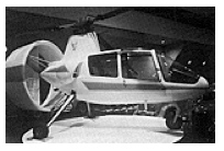
During the late 1950s and early 1960s, three commercial gyroplanes were developed and manufactured by private companies. The Umbaugh (later the Air and Space 18A), the Avian, pictured below, (a Canadian design of that same period that reached FAA certification, but was never produced) and the McCulloch J-2, each having two seats, were FAA type certified. The designers of these three aircraft, however, did not fully use the gyroplane technology created by their 1930s predecessors. In fact, to make certification easier, they used rotor head and blade technology from the helicopter industry (omitting the most valued component of that technology, the collective pitch control).
Pitcairn and Kellett (and others such as Goodyear Rubber, Autogyro Company of America, Buhl and Alfaro) had learned things about gyroplane aerodynamics, disk loading, power loading and so forth that were overlooked in these three designs. The twist in the rotor blades of a helicopter, for instance, is backward from what would be useful in a gyroplane. Disk loadings were too high and power loadings were too low. As a result, they did not perform well and the companies failed. The Umbaugh and the McCulloch each delivered about 100 units.
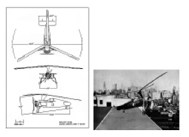
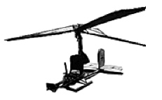
Also during the 1950s, Igor Bensen, a colleague of Igor Sikorsky, developed a home-built kit gyroplane for amateurs. He called it the ‘gyrocopter’. His idea for this open-frame model came from a German observation gyroplane (above) towed behind U-boats during the war. Home-built kits, most of which seat one person, are popular today, with more than a dozen manufacturers in the market.
Groen Brothers Aviation, Inc. thanks Mr George Townson for permission to use gyroplane photos and documentation from his outstanding book Autogiro. The Story of the “Windmill Plane”.
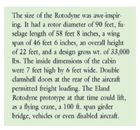
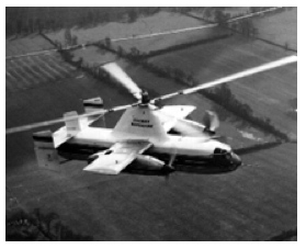
The Fairey Rotodyne
This excerpt comes from a study produced by Dr Frank Anders in 1988, and reproduced in part here, relates how the problem of gridlock at major hubs was evaluated, attacked and solved in 1957.
The Fairey Rotodyne originated from an idea for a large compound helicopter by Dr J. A. J. Bennett and Capt. A. G. Forsyth of Fairey Aviation, whose original study dates back to 1947. Their concept evolved into the ‘Eland’ Rotodyne prototype, which successfully completed its maiden flight in November 1957.
Its four-bladed rotor was powered in helicopter mode by tip jets, driven by compressed air. This compressed air was lit with fuel at tip jet combustion chambers to drive the rotor, removing the necessity for an anti-torque tail rotor. The tip jets were extinguished at about 60mph after a normal helicopter take-off, converting the aircraft to an autogyro. In autogyro mode the collective pitch of the rotor blades, and hence rotor lift, was reduced with up to about half the weight taken by the wings. This allowed much higher speeds than had previously been possible. When approaching land the tips were relit, thus converting the aircraft back to helicopter mode for a normal helicopter hover and landing.
In 1958, the Rotodyne prototype achieved economic cruise speeds of 150 knots. A world record speed of 190.9mph was set on 5 January 1959 for the 100-km closed circuit. The craft had the remarkable safety feature of being able to convert from autogiro mode to helicopter mode and hover with one engine shut down and its prop feathered. Additionally, it demonstrated safe landings in full autogiro mode.
The greatest criticism of the Rotodyne, in spite of its performance as a VTOL craft, was of the noise generated by the tip jets. The noise attenuation program at the time of cancellation had produced reductions down to the then-desired 96dB at 600ft distance. Noise critics failed to appreciate that the full power tips-lit time in service was only about one minute during take-off and climb and one minute at landing. In fact, to prove a point, test pilot Ron Gelattly made two flights over downtown London and several take-offs and landings at Battersea Heliport on a dead calm morning with no complaints raised. At the time of the project’s cancellation, the continuing development of silencers had further reduced the noise level by another 16dB. Instrument flying of the aircraft was very stable and Gelattly often demonstrated transitions from helicopter to autogyro and back again, in Instrument meteorological conditions (IMC), at less than 500ft above the ground!
The Rotodyne’s tip drive and unloaded rotor made a tremendous breakthrough in performance and handling compared to pure helicopters and other forms of convert-a-planes. The aircraft was flown at 175 knots and pulled into a steep climbing high G- turn with no adverse handling characteristics. It was demonstrated at the Farnbourgh and Paris airshows each year from 1958 to 1962 and always amazed onlookers. From any point of view the Rotodyne was an aircraft ahead of its time.
Throughout Europe and Britain, city-centre to city-centre transport was being touted as taking very little flying time. Kaman Helicopters in the U.S. was proposing a licensure for civil and military production. Interest was shown from Okanagan Helicopters Ltd. of Vancouver B.C., New York Airways, Chicago Helicopter Airways and Japan Airlines, who considered the aircraft for its Osaka–Tokyo route.
Nearly 1000 passengers, including a fair portion of the world’s airline chiefs, service chiefs and British ministers of parliament, were flown as a demonstration of the enhanced safety of the prototype in order to emphasise faith in the design.
By January of 1959, British European Airways (BEA) announced that it would write a letter of intent for six developed Rotodynes, with the hope of a requirement for up to 20 aircraft for operation on shorter routes. This was in addition to an RAF ‘order’ for 12 military transport version. In March of 1959, New York Airways planned to purchase five Rotodynes costing about 10 million dollars, with an option for an additional 15 at a later date. The U.S. Army showed considerable interest with a rumoured buy of 200 machines. None of this occurred.
Why then, was the project cancelled and the concept not pursued? Why has there not been a logical progression of existing technology dating back 40 years instead of a radical departure from that technology?
In 1959, the British Government, determined to reduce its participation in the aviation industry, reduced the number of helicopter firms. Under the direction of Minister of Aviation Duncan Sandys, the consolidation process was begun. It was done by cutting government funding. Sandys wanted one consolidated helicopter manufacturer centred on Westland aircraft. This meant that Fairey, the helicopter division of Bristol, would have to be taken over by the Westland firm.
In February 1962, the final axe fell, first with withdrawal by BEA, then the withdrawal of the military order. The world’s first vertical take-off military/civil transport died.
The Rotodyne demonstrated that a large economical VTOL airliner was a practical proposition in 1959!
All of this occurred almost 40 years ago. Had the Rotodyne persevered, accentuated with modern low fuel consumption engines and modern electronics for the hydraulic control system, commercial aviation would now have a transport of great potential competing with both fixed and rotary wing machines.
One would think such a remarkable aircraft would be retired to a prestigious position in an elite British museum. In fact, the aircraft was dismantled and destroyed, and all tooling which was used to create the Rotodyne was destroyed. Even in a search of London’s aviation museums and memorabilia, there is no evidence other than the few articles about the craft written in European and British aviation publications. A few components have been found and brought together at the International Helicopter Museum at Weston-super-Mare.
Present-day problems with air transport are much the same as they were 40 years ago, just more intense. An interesting comment was made in 1989 by Mr Michael Heatly, author of the Illustrated History of Helicopters, referring to the Rotodyne, ‘in many ways the Rotodyne was a project decades ahead of its time. Many subsequent projects from the drawing boards of the worlds’ rotorcraft manufacturers bore so little relation to this futuristic craft that it would seem more at home in the 80s skies than those of the 50s. The possibility of a similarly configured VTOL feeder liner achieving success in future decades cannot be ruled out.’